
EasyE-35

FEATURES:
- easyE-35: stroke +358 mm. If the stroke is greater than 400 mm: EL +25 mm (does not apply to the harsh-environment version; If the stroke is greater than 750 mm: EL + 100 mm (on request).
- stroke: 50, 100, 150, 200, 250, 300, 350, 400, 500 and 750mm (others on request) Note !: From stroke ≥400 limited force;
- materials: motor and actuator tube are powder coated steel or stainless steel; piston rod is aluminum; front and rear brackets are PA, Aluminium or stainless steel;
- protection class: IP66 (standard), harsh environment (according IP68 and IP69);
- power supply: 12/24VDC, see specifications
- temperature: operation: -20ºC to +70ºC; storage: -40ºC to +70ºC;
- cable: 1m, 2 x 0,52 mm² (AWG20), Ø = 4.8mm, black, Molex Mini-Fit Jr. 6 pin; see specifications
- bending radius: 6x cable diameter;
- max. static load/Self locking force:PA brackets: 2000N Alu/AISI: 5400N, depending on stroke length for push-applications;
- duty cycle: Max. 10% or 2 minutes in use followed by 18 minutes rest.
View the options for controlling and mounting the easyE-35 actuator.
CAD-Configurator

Configure quick and simply the CAD files of your easyE-35.
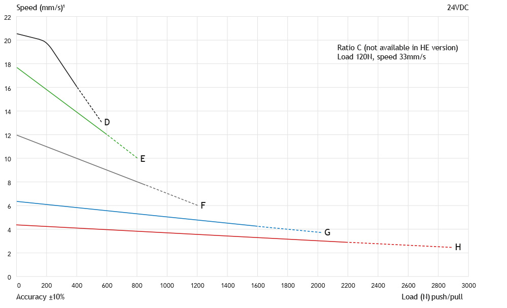
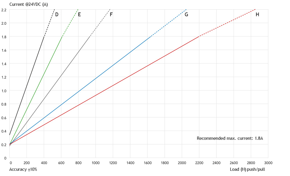
SPEED AND FORCES
| Gear ratio | C* | D | E | F | G | H |
|---|---|---|---|---|---|---|
| EasyE-35 (12/24VDC power supply, permanent magnet motor) | ||||||
| Force 24V (dyn. push and pull) (N)** | 120 | 400 | 600 | 900 | 1600 | 2200 |
| Speed at maximum load (mm/s) | 33 | 16 | 12 | 7,5 | 4 | 3 |
| Force 12V (dyn. push and pull) (N)** | - | 400 | 600 | 900 | 1500 | 2000 |
| Speed at maximum load (mm/s) | - | 16 | 9 | 7,5 | 3,5 | 2,5 |
Current at maximum load: 12VDC (max 14 VDC) = 3,6A, 24VDC (max 28 VDC) = 1,8A
* only 24V DC power supply
** max. load limited for stroke length >400mm: 1000N
| EL | Clevis rear | Hall sensor | UL/EN60.601 | Harsh environment | |
|---|---|---|---|---|---|
| EasyE-35 | |||||
| Gear ratio: C, D, E, F | stroke +160* | +10 | +10 | +10 | +11 |
| Gear ratio: G, H | stroke +170* | +10 | +10 | +10 | +11 |
* stroke length >400mm: EL +7, stroke > 700: EL +42
* Axial backlash: ±-0,5mm - generally length tolerance ±-1mm
Dimensions

Weight of the actuators
| Stroke length (mm) | 50 | 100 | 150 | 200 | 250 | 300 | 350 | 400 | 500 | 750 |
| Weight (kg) | 0,8 | 0,9 | 1,0 | 1,1 | 1,2 | 1,3 | 1,4 | 1,6 | 1,8 | 2,3 |
Actual weight may vary depending on model and options selected.
Speed/Force (12VDC)

Force/Current (12VDC)

Speed/Force (24VDC)
Force/Current (24VDC)
CONNECTING PARTS "MOTOR-SIDE":
HINGE EYE

HINGE EYE WITH SPHERICAL BEARINGS

CLEVIS


CONNECTING PART "PISTON-ROD-SIDE":
HINGE EYE

HINGE EYE WITH SPHERICAL BEARINGS

CLEVIS

RECOMMENDED MOUNTING METHODS
- Do not clamp actuators on tubing
- Always keep both brackets mounted in the same orientation and ensure to flush mount actuator
- Brackets must always be able to rotate on axels in mountings
FOR THE FIXATION OF THE EASYE-LINE ACTUATORS WE OFFER THE FOLLOWING BRACKETS:
Motor side

Piston rod side


PLEASE NOTE
- Power supply without over-current protection can cause serious damage to the actuator at mechanical end-stop or when actuator is overloaded in another way
- Radial forces might have an adverse affect on the performance or lead to damage of the actuator
- Keep piston tube clean
- Longer cable lengths may cause voltage drop which affects the performance of the actuator
- For medical applications (IEC60601-1, ANSI/AAMI/ES60601-1, CAN/CSA-C22.2 No60601-1): Operating temperature +5ºC to +48ºC, Relative humidity 20% - 70% atmospheric pressure = 1atm. Connect to medically approved supply source only and according to guidelines provided with the source
- The dust and water sealing of "harsh environment" actuators might affect their performance
- All specifications are for 25 ºC ambient – low temperature might affect performance
- Depending on load and application, nominal and actual stroke length may differ due to internal disc springs not being fully compressed
- The combination of gearing and stroke can cause limitations in the use of „End limit FW“ when using the S2-3 controller. See more in the datasheet for S2-3.