
EasyE-50i
The new "intelligent" in-line actuator
In-line actuators with integrated controller (easyE-i) enable the use of MODBUS RTU on an RS485 serial communication. One of the most powerful standards. The easyE-i options provide everything from simple maintenance, control and installation, to a wide range of customizable settings and feedback that will help tailor the movement solution to your specific needs and application.
Integrated controller functions:
- adjustable start ramp;
- adjustable stop ramp;
- adjustable current limit;
- industrial interface MODBUS RTU on RS485;
- internal stroke limitation;
- internal heat protection;
- plug & play solution with iConnect-Box and handset.
Specifications:
- easyE-50i: stroke +255 mm (C, D, E, F), stroke + 270 mm (G, H). If stroke is larger than 750 mm: EL + 7 mm (on request);
- max. load: 4500N (depending on the ratio);
- materials: motor and actuator tube are powder coated steel (other RAL colors on request) or stainless steel; piston rod is aluminum; front and rear brackets are PA, Aluminium or stainless steel;
- power supply: 12/24VDC, see specifications
- protection class: IP66 (standard), harsh environment (according IP68 and IP69);
- temperature: operation: -20ºC to +70ºC; storage: -40ºC to +70ºC;
- cable: 1m, 2X0.65mm² (AWG16), Ø = 6,4 mm, black, Molex Mini-Fit Jr. 8 pin; see specifications
- bending radius: 6x cable diameter;
- max. static load/Self locking force:PA brackets: 2000N Alu/AISI: 5400N, depending on stroke length for push-applications;
- duty cycle: Max. 10% or 2 minutes in use followed by 18 minutes rest.
For more information on Modbus RTU please go to https://modbus.org/specs.php. MODBUS over serial line specification and implementation guide V1.0. View the possibilities for controllers and mounting parts and brackets of the easyE-50i actuator.
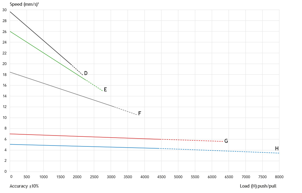
| Gear ratio | C* | D | E | F | G | H |
|---|---|---|---|---|---|---|
| EasyE-50i (12/24VDC power supply, permanent magnet motor) | ||||||
| Force 24V (dyn. push and pull) (N)** | 500 | 1750 | 2200 | 3100 | 4500 | 4500 |
| Speed at maximum load (mm/s) | 70 | 20 | 17 | 12 | 6 | 4 |
| Force 12V (dyn. push and pull) (N)** | - | 1400 | 1700 | 2400 | 4500 | 4500 |
| Speed at maximum load (mm/s) | - | 14 | 10 | 6 | 3 | 3,5 |
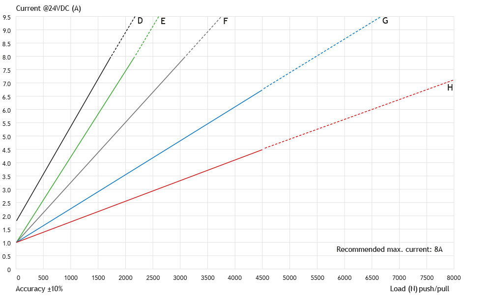
Current at maximum load: 12VDC (max 14 VDC) = 16A (ratio C-F), 14A (ratio G), 9A (ratio H), 24VDC (max 28 VDC) = 8A (ratio C-F), 7A (ratio G), 4,5A (ratio H)
* only 24V DC power supply
** Max. loadl imited for stroke length >400mm: 2000N
| EL | UL/EN60.601 | Harsh environment | |
|---|---|---|---|
| EasyE-50i | |||
| Gear ratio: C, D, E, F | stroke +255* | +15 | +14 |
| Gear ratio: G, H | stroke +270* | +15 | +14 |
* stroke length >750mm: EL +100mm (on request)
* axial backlash: ±-0,5mm - generally length tolerance ±-1mm
DIMENSIONS

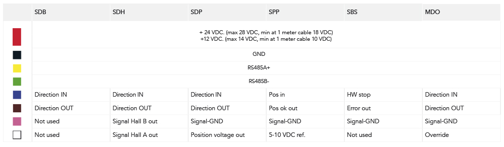
| Configuration P/N letter Description |
SDB (S2-1) A Single/Direction/Basic |
SDH (S2-1+hall) B Single/Direction/Hall |
SDP (S2-1+pos. out) C Single/Direction/Position |
SPP (S2-2) D Single/Direction/Position |
SBS (bus-based) E Single/Bus/Status |
MDO (synchronization) F Multiple/Direction/Override |
|---|---|---|---|---|---|---|
| 1 | +12/24VDC | +12/24VDC | +12/24VDC | +12/24VDC | +12/24VDC | +12/24VDC |
| 2 | PWR GND | PWR GND | PWR GND | PWR GND | PWR GND | PWR GND |
| 3 | RS485A | RS485A | RS485A | RS485A | RS485A | RS485A |
| 4 | RS485B | RS485B | RS485B | RS485B | RS485B | RS485B |
| 5 | Input: Direction IN | Input: Direction IN | Input: Direction IN | Output: Ref. 5/10VDC | Input: STOP | Input: Direction IN |
| 6 | Input: Direction OUT | Input: Direction OUT | Input: Direction OUT | Input: Position (analog) | Output: Error | Input: Direction Out |
| 7 | Output: Hall A | Output: Position (analog) | in/output: STOP/Pos.OK | Input: Override | ||
| 8 | Output: Hall B |
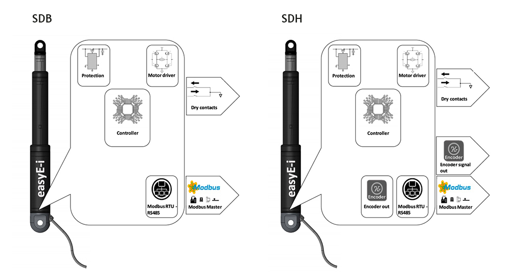
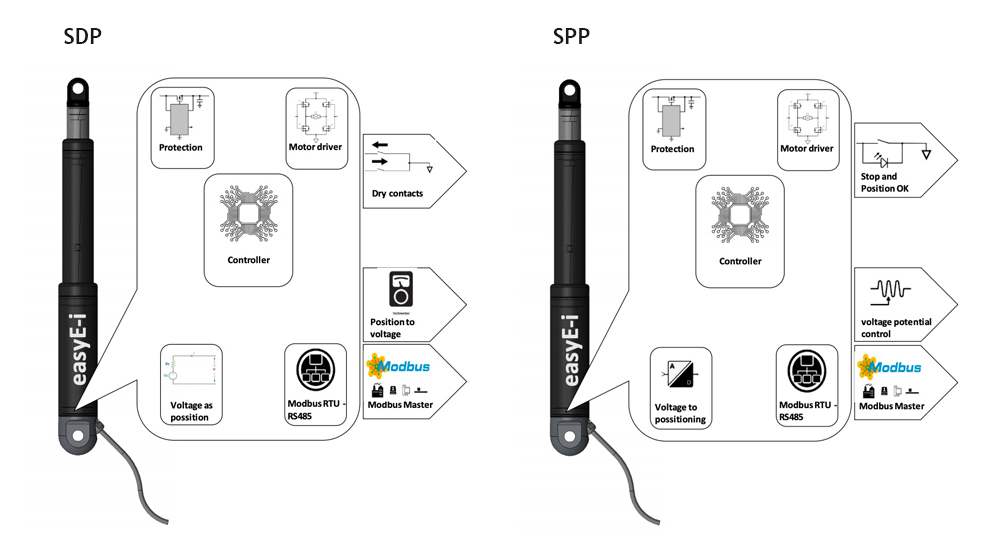
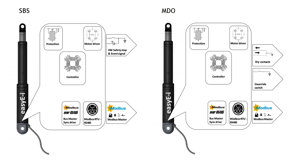
Electrical wiring

Electrical data
Max. current load:
- easyE-35i: 2 ADC @ 24 VDC, 4 ADC @ 12 VDC
- easyE-50i: 8 ADC @ 24 VDC, 16 ADC @ 12 VDC
- easyE-60i: 16 ADC @ 24 VDC
Idle current: +- 10 mADC
Current trip delay: 20 ms
PWM frequency: 25 kHz
Digital inputs: ‘High’: Uin = 4 Vdc - Vsupply; ‘Low’: Uin = 0 Vdc - 1 Vdc
Supply voltage:
- 12 VDC (min 10 VDC at 1 meter cable, max 14 VDC) or
- 24 VDC (min 20 VDC at1 meter cable, max 28 VDC)
Serial data line: RS485 asynchronous, "point to point" or "multi-point", 2 wire half-duplex.
Communication: Modbus RTU
Bauds rate: 115000 bps
Com setup: 8 Bit, Parity -None, Stop bit -1
PLEASE NOTE
- power supply without over-current protection can cause serious damage to the actuator at mechanical end-stop or when actuator is overloaded in another way;
- radial forces might have an adverse affect on the performance or lead to damage of the actuator;
- keep piston tube clean;
- longer cable lengths may cause voltage drop which affects the performance of the actuator;
- for medical applications (IEC60601-1, ANSI/AAMI/ES60601-1, CAN/CSA-C22.2 No60601-1): Operating temperature +5ºC to +48ºC, Relative humidity 20% - 70% atmospheric pressure = 1atm. Connect to medically approved supply source only and according to guidelines provided with the source;
- the dust and water sealing of "harsh environment" actuators might affect their performance;
- all specifications are for 25 ºC ambient – low temperature might affect performance;
- depending on load and application, nominal and actual stroke length may differ due to internal disc springs not being fully compressed;
- the combination of gearing and stroke can cause limitations in the use of „End limit FW“ when using the S2-3 controller. See more in the datasheet for S2-3.
Accessories EasyE-i-Connect
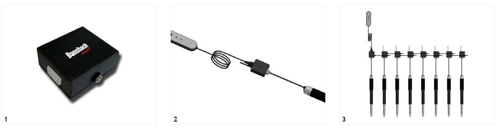
1. Easy connection to: BUS, Handset and Power supply. This is only a connection device, without integrated intelligence.
2. i-Connect box for easy connection to BUS and Handset.
3. Easy cascading of more i-Connect boxes to synchronization up to 8 actuators. Controll option by Handset and BUS.
WEIGHT OF THE ACTUATORS
| Stroke length (mm) | 50 | 100 | 150 | 200 | 250 | 300 | 350 | 400 | 500 | 750 |
| Weight (kg) | 2,1 | 2,3 | 2,6 | 2,8 | 3,1 | 3,3 | 3,6 | 3,8 | 4,3 | 5,6 |
Actual weight may vary depending on model and options selected.
SPEED/FORCE (12VDC)

FORCE/CURRENT (12VDC)

SPEED/FORCE (24VDC)
FORCE/CURRENT (24VDC)
CONNECTING PARTS "MOTOR-SIDE":
HINGE EYE


CONNECTING PART "PISTON-ROD-SIDE":
HINGE EYE

RECOMMENDED MOUNTING METHODS
- do not clamp actuators on tubing;
- always keep both brackets mounted in the same orientation and ensure to flush mount actuator;
- brackets must always be able to rotate on axels in mountings.
FOR THE FIXATION OF THE EASYE-LINE ACTUATORS WE OFFER THE FOLLOWING BRACKETS:
Motor side

Piston rod side

